





Touch panel testing before human-machine interface (HMI) integration should confirm that input is detected, reported in the correct area and released correctly. A useful bench check covers individual points and continuous movement, then records the panel configuration and observations for the next assembly stage.
The VANESEN workshop video shows a front panel being operated at a laptop-connected bench, followed by views of protected panels and equipment loading. This article uses that footage to explain a practical pre-integration checklist. The checklist is proposed guidance; the video does not provide a readable inspection report or acceptance limits.
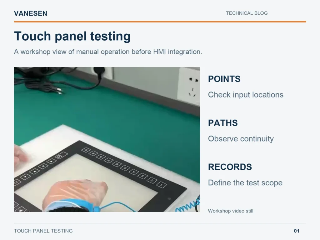
Workshop footage: the panel is supported on a bench during manual operation. The image does not establish a pass result.
Start with a defined test setup
A touch response is meaningful only when the setup is known. Identify the panel revision, controller, connection arrangement and software configuration before starting. Confirm the intended orientation and coordinate mapping, particularly when the host has more than one display.
Support the panel without loading its active surface or pulling its cable. Follow the component supplier’s handling and electrostatic discharge (ESD) precautions. A glove visible in a workshop scene does not, by itself, demonstrate glove-operation performance or compliance with an ESD control procedure.
If the host does not recognize the device, establish the connection and configuration first. Keep this separate from a panel that connects successfully but reports incorrect positions. The distinction makes the next troubleshooting step clearer.
Touch panel testing: check points and paths
A single successful tap confirms very little about the rest of the input area. Use an agreed pattern that includes the center, positions near the corners and representative edge locations, all within the specified active area. Add locations corresponding to important controls in the intended application.
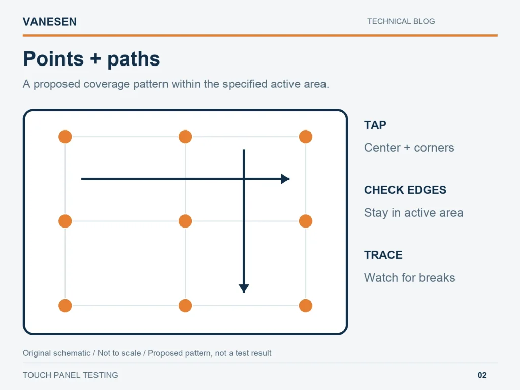
Original schematic, not to scale. Targets illustrate coverage; their positions and acceptance limits must be defined for the actual panel.
| Check | What to observe | What to record |
|---|---|---|
| Individual targets | Whether the reported point corresponds to the intended location | Target, observed offset or missed input |
| Touch and release | Whether input begins and ends as intended | Missed activation, unexpected repeat or retained contact |
| Continuous paths | Whether movement produces a continuous trace | Breaks, jumps or areas that cannot be reached |
| Repeated locations | Whether the same operation produces consistent observations | Location and conditions of any recurring symptom |
Use the supplier-approved finger or test tool and the agreed input conditions. A quick manual trace can reveal an obvious discontinuity, but it does not establish numerical accuracy, jitter or latency. Those claims require a defined measurement method and recorded data.
The printed symbols around a panel are also separate from proof of function. Confirm whether each marked area is an active input, an independent key or only a legend, then include the required functions in the project test plan.
Keep calibration separate from verification
Where supported and required, calibration adjusts the relationship between sensed input and reported coordinates. Verification checks the resulting behavior against acceptance criteria. Calibration is not a universal remedy, and the available procedure depends on the touch technology and controller.
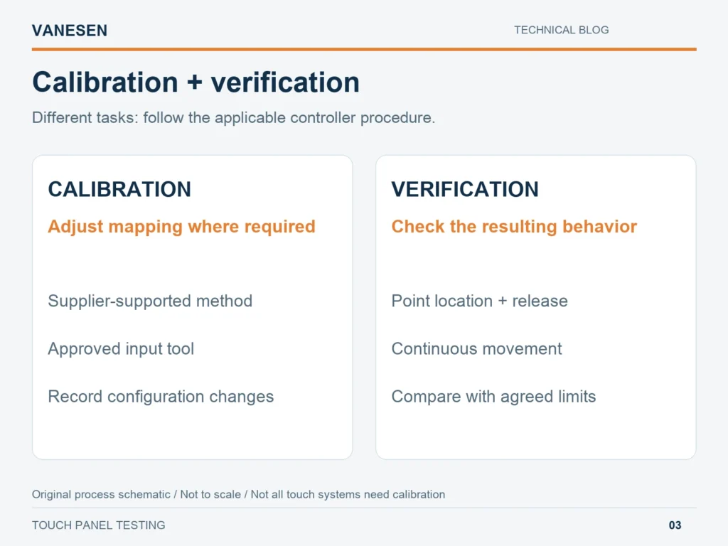
Original process schematic, not to scale. Follow the applicable controller documentation; the video does not identify a calibration procedure.
After an authorized adjustment, repeat the affected checks and record the configuration change. If a symptom persists, preserve the initial observations and inspect the connection, mapping and supported mounting arrangement before changing further settings. Changing several variables together makes the cause harder to isolate.
Touch input and display appearance also need separate checks. A visible image does not prove correct input registration, and a responding touch sensor does not establish display uniformity or image quality.
Record the result before the next assembly stage
The later workshop views show panels individually protected on the bench. Protection during transfer matters because a completed check should remain linked to the correct physical part and its current condition.
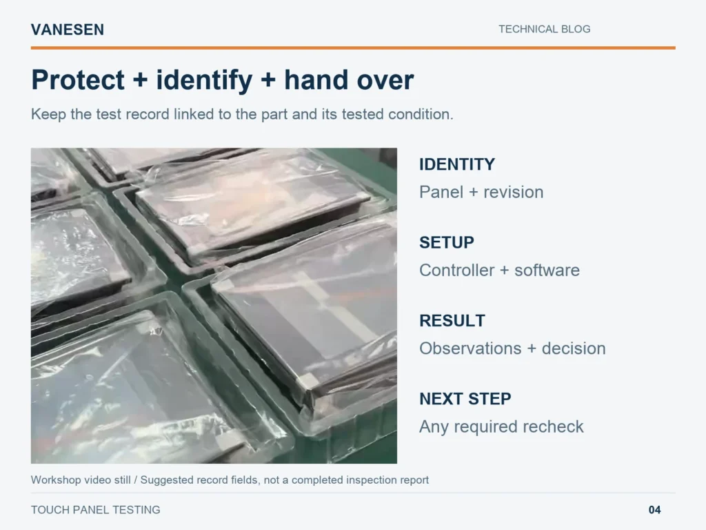
Workshop footage with an editorial handover checklist. Transparent protection is visible; its material specification is not established by the video.
A practical handover record should include:
- Panel identity and drawing revision, with customer-sensitive identifiers kept out of public images.
- Controller and software configuration, test method and applicable acceptance criteria.
- Actual observations, result, operator and date, with unresolved issues clearly identified.
- Any later operation that requires another check under the approved inspection plan.
For example, if subsequent mounting or processing changes the tested configuration, define the necessary verification at that stage. A bench record applies to the condition tested; final assembly acceptance requires its own agreed scope. VANESEN’s HMI first article inspection guide provides related context for agreeing inspection requirements.
Define what the bench check can establish
The footage also shows a panel being loaded into a chamber. It does not establish the process recipe, cycle completion or resulting performance. Temperature, pressure and process purpose therefore cannot be inferred from that scene.
Likewise, a short manual demonstration cannot establish environmental durability, ingress protection or industry certification. Keep the release decision tied to the specified tests and their records.
For a project review, share the panel model, controller information, assembly drawing, intended input method and acceptance requirements. Explore VANESEN’s Display- und HMI-Baugruppe und Prüfung und Lieferung services, or Kontaktieren Sie VANESEN to discuss the required inspection scope.