Optical Bonding & Display Integration for Industrial HMI

From your initial design to a tested HMI assembly. We bring together engineering, component sourcing, metal enclosure manufacturing, optical bonding, assembly and testing.

DISPLAY & HMI INTEGRATION

Every layer.
One complete HMI.

From the cover glass to the metal enclosure, explore how the optical stack, controls and electronics come together.

01

A coordinated optical stack

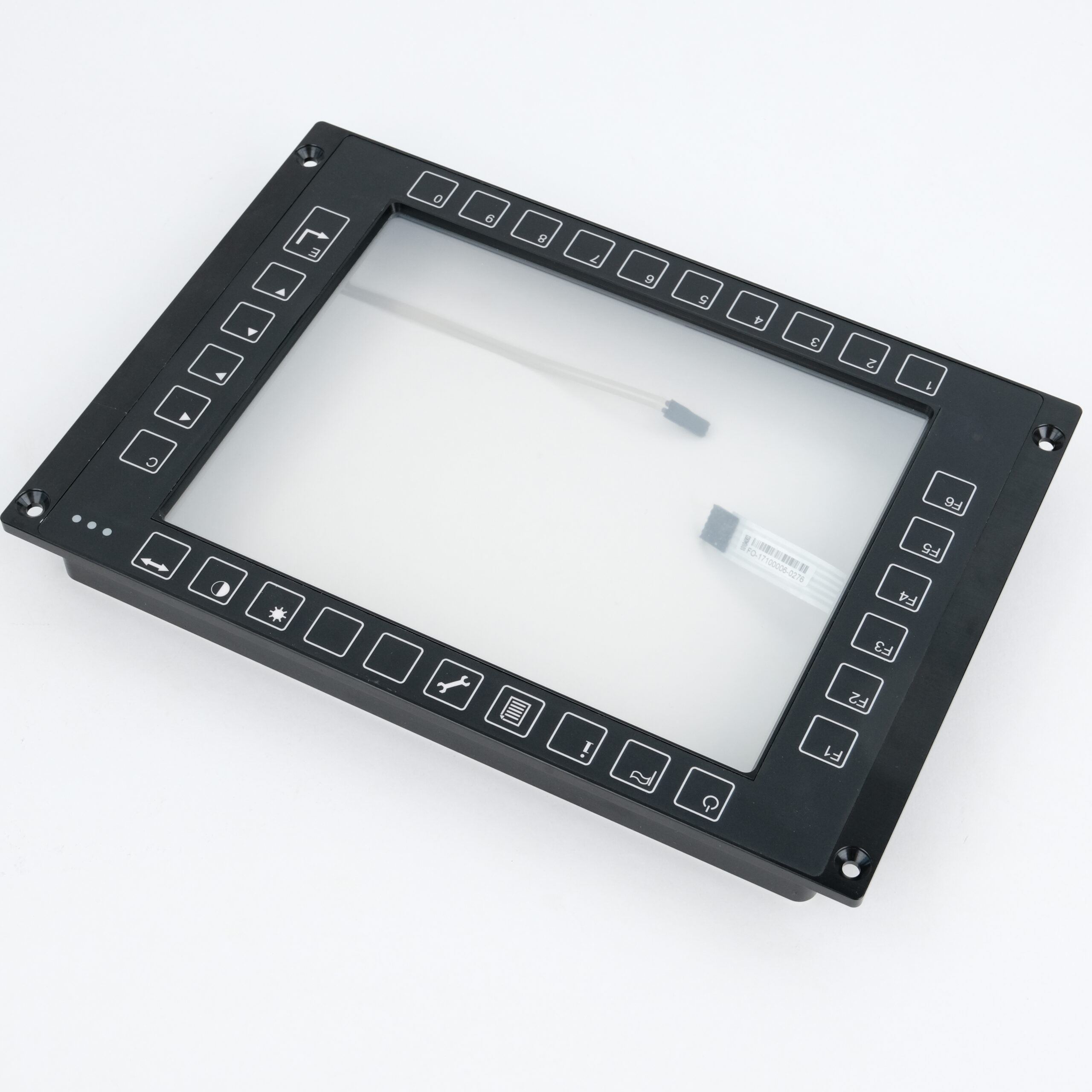
Cover glass, touch sensor, optical adhesive and LCD designed around one viewing window.

02

Touch and keypad, aligned

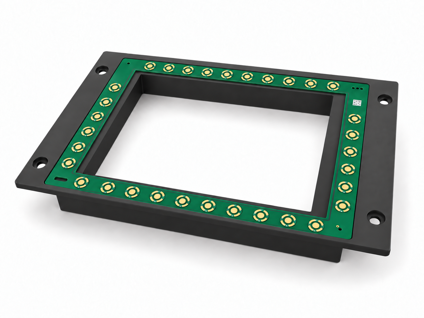
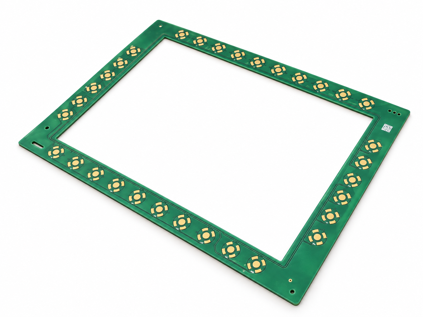
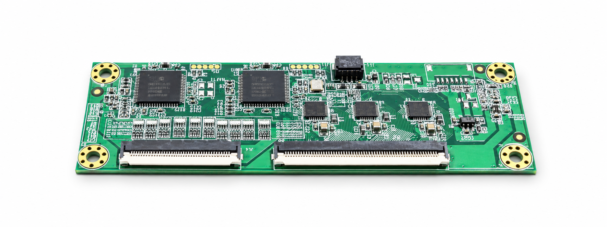
Printed keys align with the front PCBA. The touch controller sits inside the enclosure with short FPC connections.

03

Integration down to the enclosure

Graphite metal panels, rear cooling fins and accessible board-level assemblies bring the mechanical and electronic design together.

Illustrative assembly. Dimensions, interfaces and performance requirements are defined for each project.

EXPLORE THE ASSEMBLY

INTERACTIVE 3D

Drag a part to move along the assembly axis. Drag the background to rotate. Scroll or pinch to zoom. Use Explode to explore each layer.

FROM YOUR BRIEF TO AN INTEGRATED HMI

Your concept. Our engineering. A complete HMI.

Four connected stages align your requirements, engineering design, component choices and final assembly.

01 / YOU PROVIDE

Requirements
& Sketches

Start with your application, a concept sketch or an existing drawing. We turn these inputs into a clear project brief.

Mechanical inputs
Panel opening, mounting points, installation space and enclosure constraints.

Functional targets
Display size, touch or keypad operation, interfaces and operating environment.

OUTPUT · Agreed design brief

02 / WE DESIGN

Engineering
Design

Develop the mechanical and electrical layout around the intended user interface and installation envelope.

Structure & layout
Front frame, key positions, fixing points, clearances and component alignment.

Design review
Optical stack, cable routing, assembly sequence and manufacturability.

OUTPUT · Reviewed integration layout

03 / WE SELECT

Component
Selection

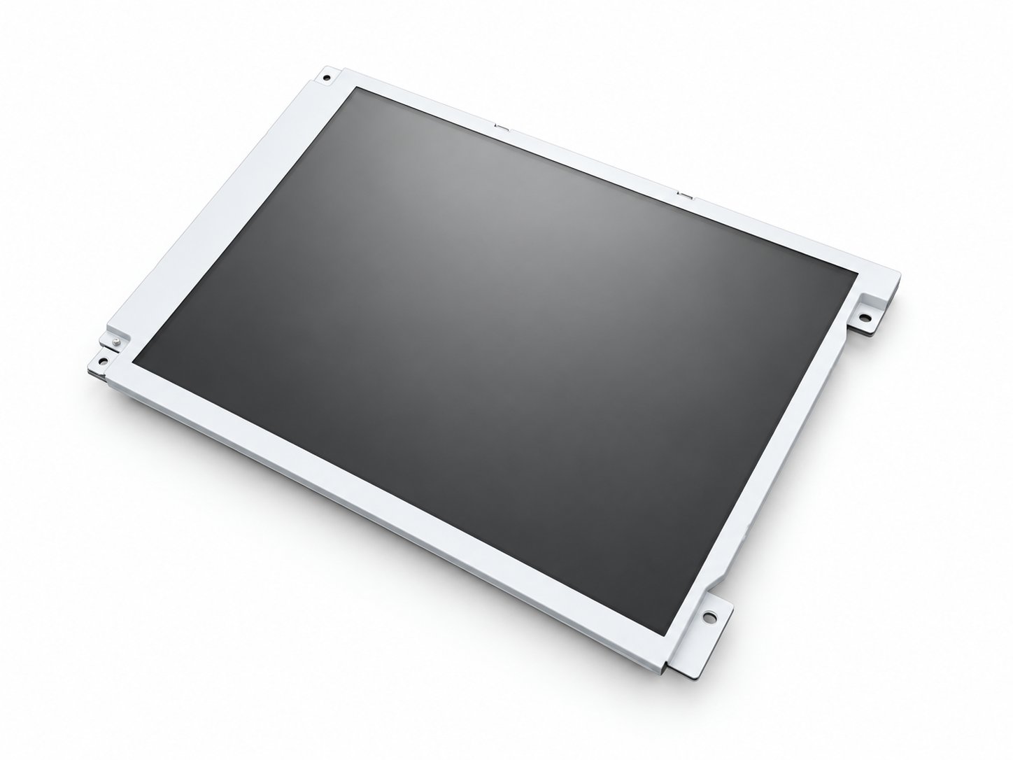
LCD display

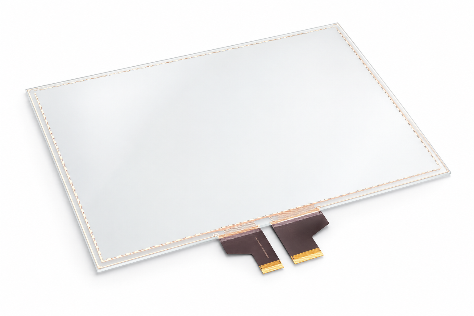
Touch panel (TP)

Keypad PCBA

Touch controller

Match the display, touch panel, keypad electronics and controller as one coordinated component set.

Optical matching
LCD size, resolution and brightness; touch technology and cover requirements.

Electrical matching
Controller compatibility, connectors, power requirements and component availability.

OUTPUT · Matched component list

04 / WE INTEGRATE

System
Integration

Bring the optical, mechanical and electronic elements together in a complete display or HMI assembly.

Build & assemble
Optical bonding, keypad and display fitment, cable connection and enclosure assembly.

Verify function
Inspect appearance, alignment, display output and touch or keypad response.

OUTPUT · Integrated HMI assembly

Illustrative project shown. Materials, performance targets and verification scope are agreed for each application. Select an image to view its details.

Custom Display Integration, from Design to Delivery

One coordinated process for your optical, mechanical and assembly requirements.

TWO CORE MANUFACTURING CAPABILITIES

Optical Bonding & Metal Manufacturing

Coordinated around the same HMI design—from the optical stack to the enclosure.

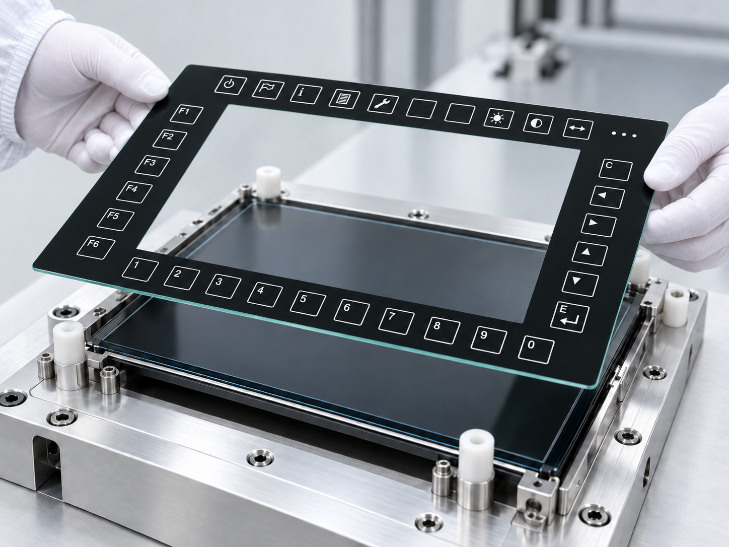
Optical bonding illustration with icon-printed cover glass aligned above an LCD module.
01

Optical Bonding

Bond cover glass, touch sensors and LCDs into an integrated optical stack.

Cover glass / Touch sensor / LCD

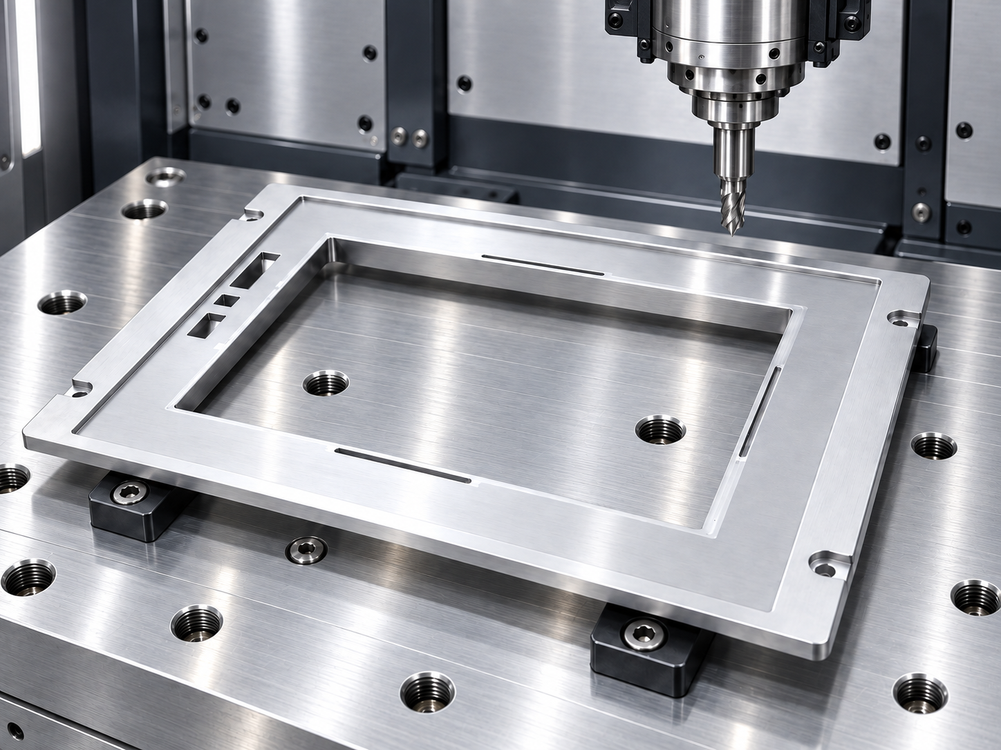
CNC machining illustration showing a spindle and cutting tool above an aluminum HMI front frame on a precision worktable.
02

Metal Structure Manufacturing

Precision-machined frames and enclosures developed around your approved HMI layout.

Machining / Dimensional inspection / Trial fit

Two capabilities. One complete HMI assembly.

Optical, mechanical and assembly requirements developed together.

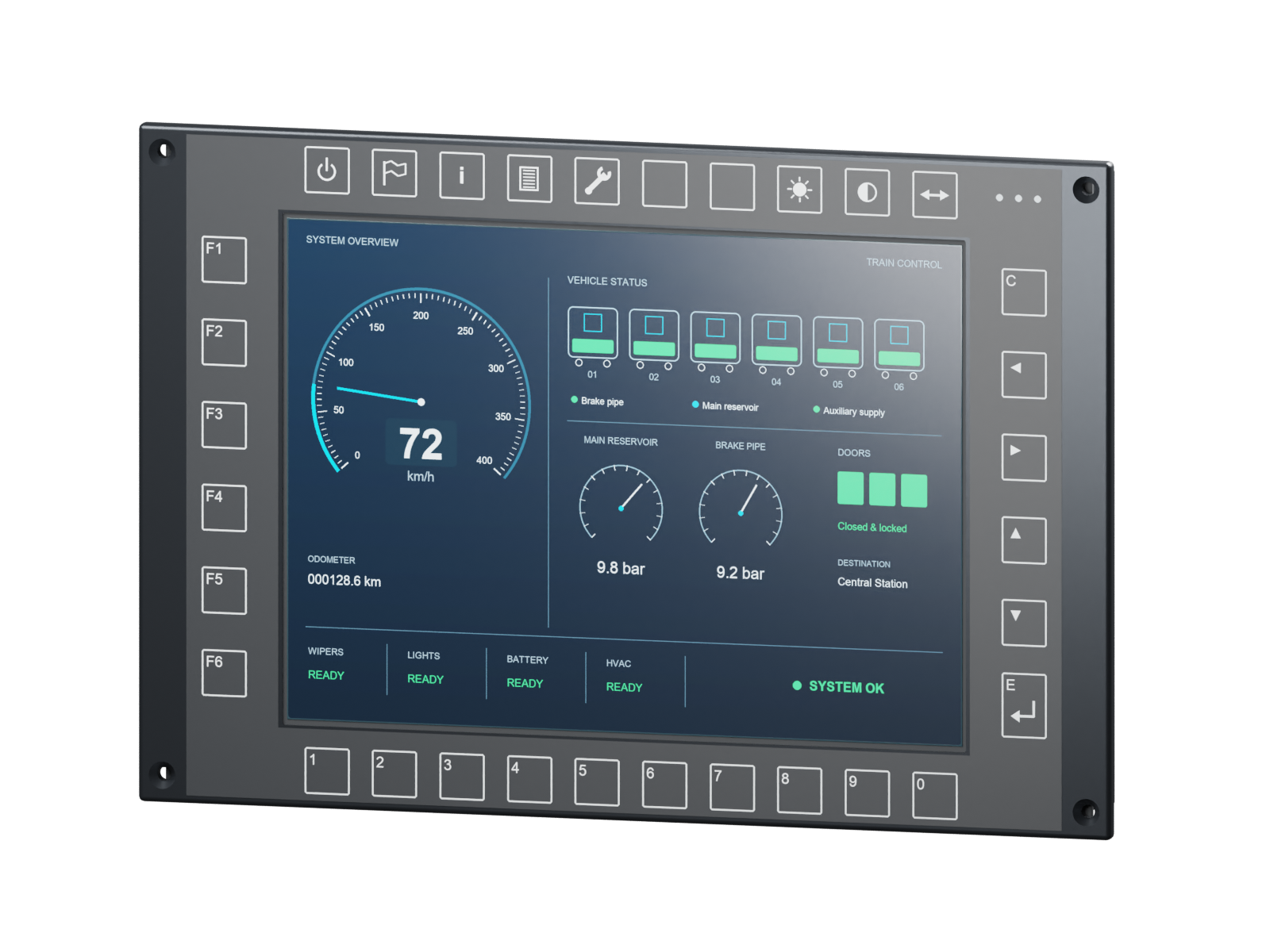
Railway cab display application illustration

Industrial Display Integration for Railway Applications

Optical bonding and mechanical integration built to withstand vibration, shock and temperature.

-40°C to +85°C

IP65

Vibration

Project targets. Scope and verification defined per application.

WHY VANESEN

One coordinated path to a complete HMI.

Your display, touch interface, electronics and enclosure must work as one product. We coordinate the engineering and manufacturing steps around that complete assembly.

01

A coordinated project workflow

Start with a concept, preliminary drawing or display requirement. We connect layout development, component selection, manufacturing, assembly and testing through an agreed project scope, so decisions are made with the final HMI in mind.

PROJECT FOCUS

Agreed requirements • Reviewed layout • Defined delivery scope

02

Optical and mechanical fit, together

We consider the cover glass, touch sensor, LCD, controller and metal enclosure as a connected system. Optical stack-up, viewing area, mounting points, interfaces and cable routing are reviewed together to support a compatible assembly.

ENGINEERING FOCUS

Optical stack-up • Component fit • Cable and interface layout

03

Designed for manufacturing and assembly

A design must be practical to build. We review structure, clearances, fixing methods and assembly sequence, then coordinate metal-part manufacturing and trial fit around the approved layout before progressing to the complete assembly.

BUILD FOCUS

Manufacturability review • Metal parts • Trial assembly

04

Verification tied to the agreed requirements

Delivery includes more than a finished appearance. Display and touch function, optical condition, mechanical fit and interfaces are checked against the agreed scope. Environmental testing and delivery documentation are defined for each project.

DELIVERY FOCUS

Functional checks • Inspection records • Project documentation

Clear inputs. Defined work. A complete deliverable.

Bring your application requirements, drawings or LCD model. We will help define the next engineering step.

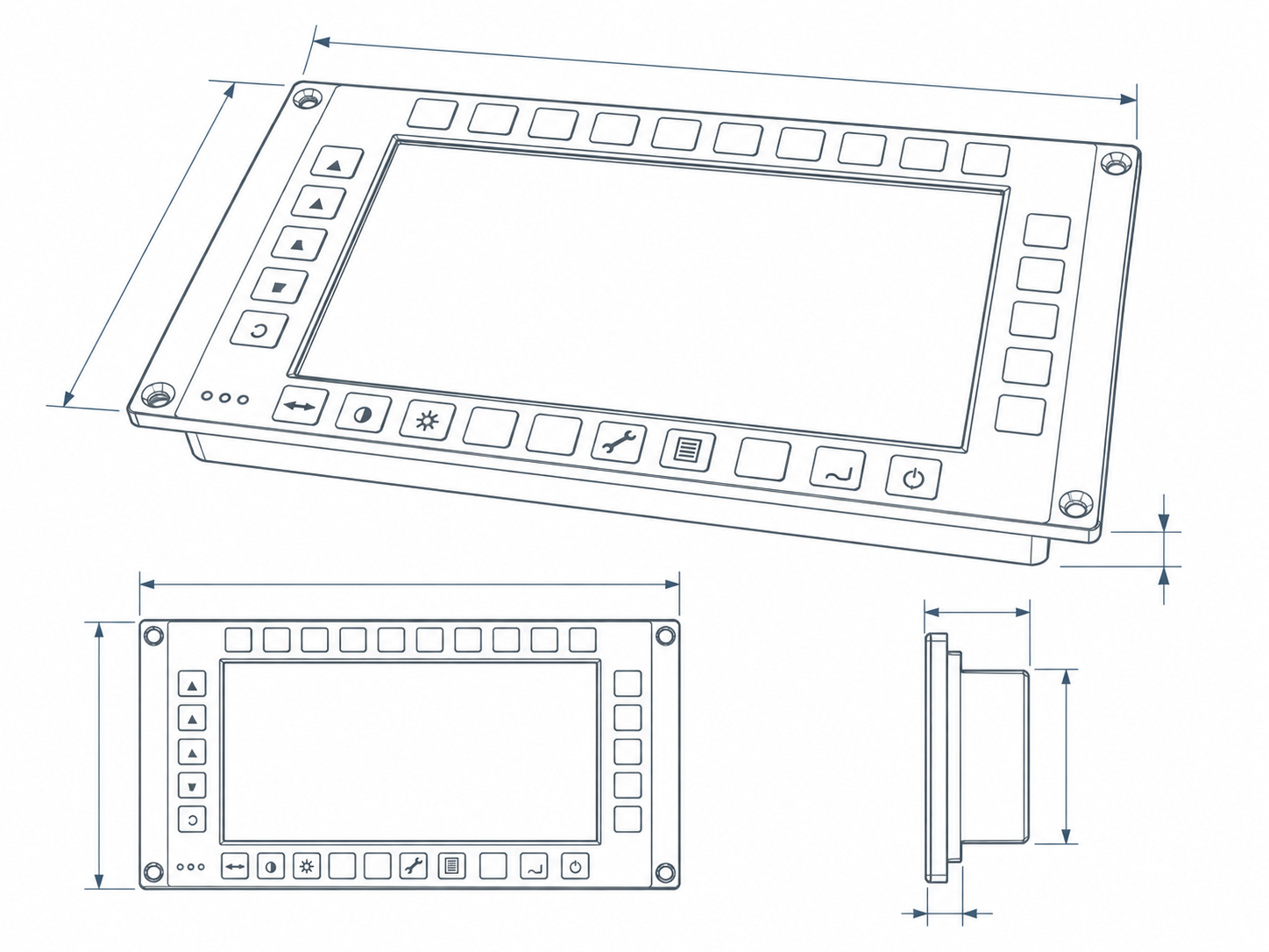
Project scope, specifications, testing and documentation are confirmed for each application.

Global collaboration

Optical bonding and custom HMI solutions for international projects.

World map with illustrative location markers for international collaboration

START YOUR PROJECT

Your next HMI starts with a conversation.

Bring a concept, a drawing or an existing display. We will help define a practical path to your complete assembly.

Concept or drawing

A sketch, reference product or preliminary design.

Display requirements

LCD size or model, touch, keypad and interfaces.

Application needs

Installation space, operating environment and quantities.

A preliminary idea is enough. Drawings can follow later.

What happens next:

Review your information

Clarify requirements

Define the next step

Project scope, testing and deliverables are confirmed for each application.