
Home / Metal Structure Manufacturing
03 / METAL STRUCTURE MANUFACTURING
HMI Enclosure Manufacturing
We manufacture the metal frames, enclosures and mounting features that bring the display, touch interface and electronics together as one integrated product.
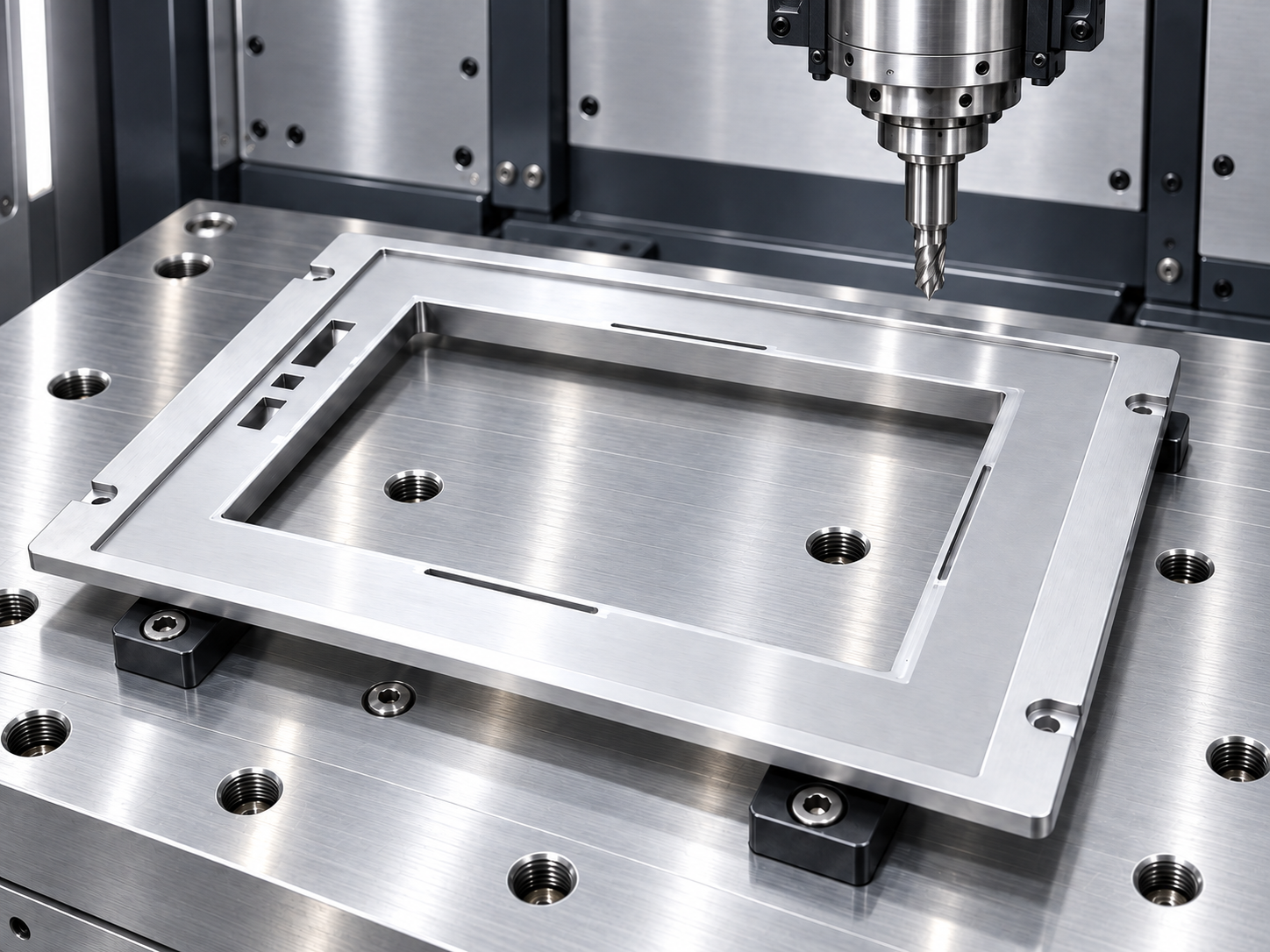
From CNC programming to part inspection.
A clear sequence connects the engineering drawing, machine setup, production and dimensional checks.
01
CNC programming
02
CNC machine setup
03
Production machining
04
Semi-finished part inspection
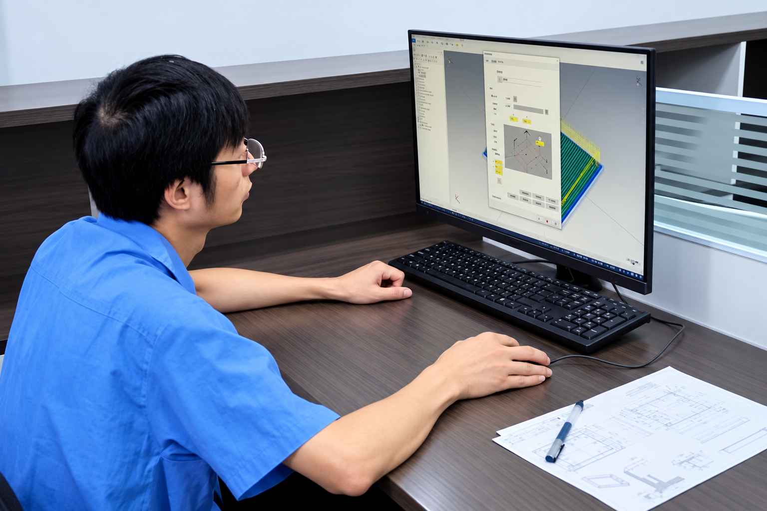
CNC programming.
01 / CNC PROGRAMMING
Turn the drawing into a machining plan.
CNC programming translates the engineering drawing into the machining sequence. The part geometry provides the basis for planning how the metal structure will be produced.
- Review the drawing revision and part geometry
- Plan machining operations for the specified features
- Prepare the CNC program for machine setup
Drawing requirements guide the work. Material, dimensions and any specified finish need to be agreed for the project.
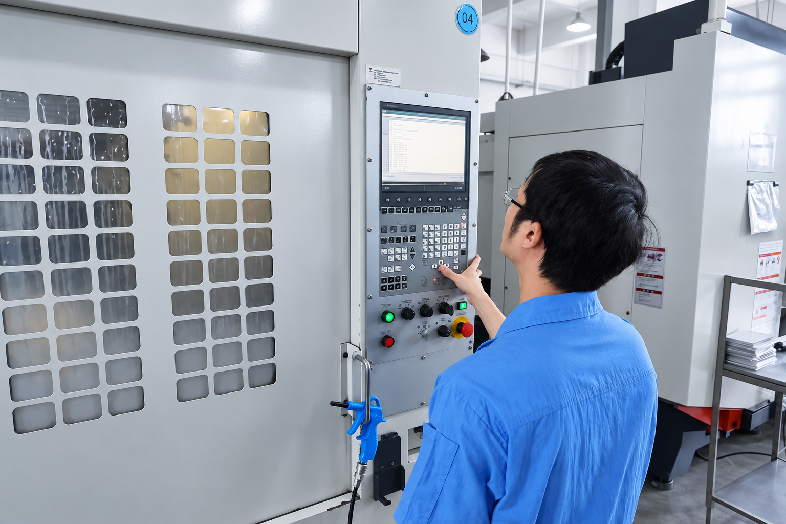
CNC machine setup.
02 / CNC MACHINE SETUP
Prepare the machine for the planned work.
The engineer sets up and adjusts the CNC equipment for the prepared program. This stage connects the machining plan with the machine and the workpiece.
- Set up the workpiece location and holding arrangement
- Prepare the tools and machining references
- Review the program and setup before production
Setup requirements depend on the part and the machining operation.
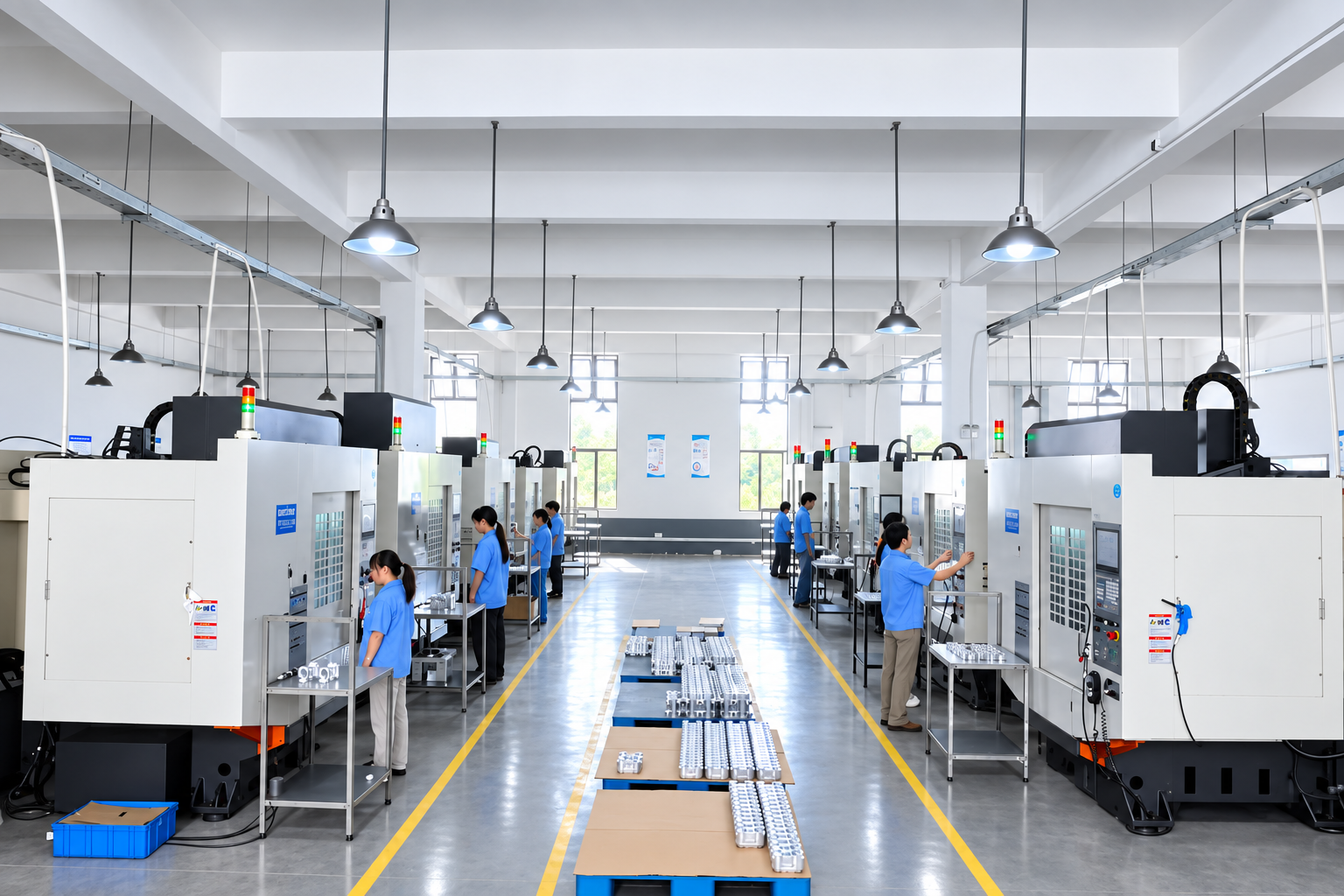
Production machining.
03 / PRODUCTION MACHINING
Machine the metal structure.
Operators run the CNC equipment to produce the metal parts. For an HMI structure, the drawing defines the display opening, mounting features and other required interfaces.
- Follow the prepared machining program
- Monitor the equipment during the operation
- Produce the features specified on the part drawing
Front frames, rear enclosures and internal supports have different machining requirements; the drawing defines the scope.
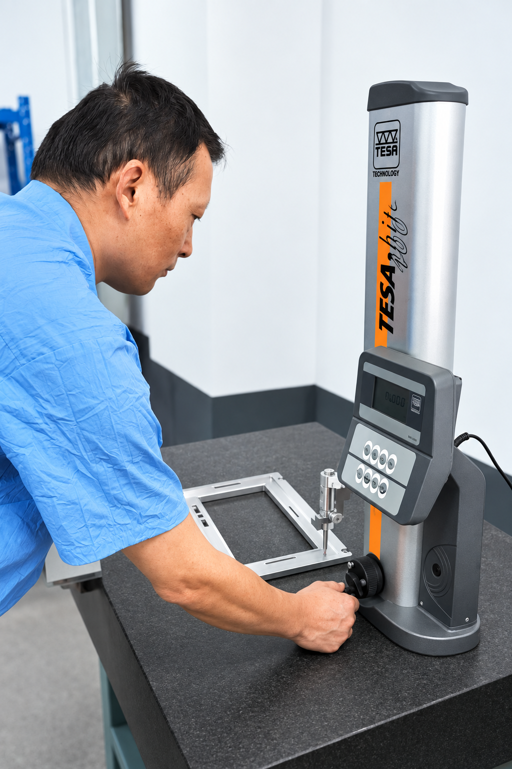
Illustrative composite based on the supplied inspection photograph and approved front-frame image.
04 / SEMI-FINISHED PART INSPECTION
Check the part before the next operation.
The engineer checks the semi-finished metal part against the drawing requirements. This stage concerns the machined part, before the subsequent operations defined for the project.
- Check the specified dimensions and reference surfaces
- Review the relevant mounting and interface features
- Resolve dimensional findings before the next operation
The height gauge shown is one inspection tool. Other checks and instruments depend on the drawing; this image does not represent complete product validation.
Keep the next assembly step in view.
Dimensional checks are part of the route to an approved metal structure. Where the project requires it, trial fit reviews how the machined parts work with the mating components.
Mechanical interfaces
Review the front-to-rear fit, fixing positions and installation interface against the agreed design.
Component clearances
Review the space for the display, PCBA supports, connectors and cables during trial fit.
Any surface finishing, marking, further inspection and release requirements are defined for the project. Semi-finished inspection is not final HMI testing or shipment approval.
Discuss your metal structure.
Share your drawings, material requirements and assembly interfaces so the manufacturing scope can be defined.