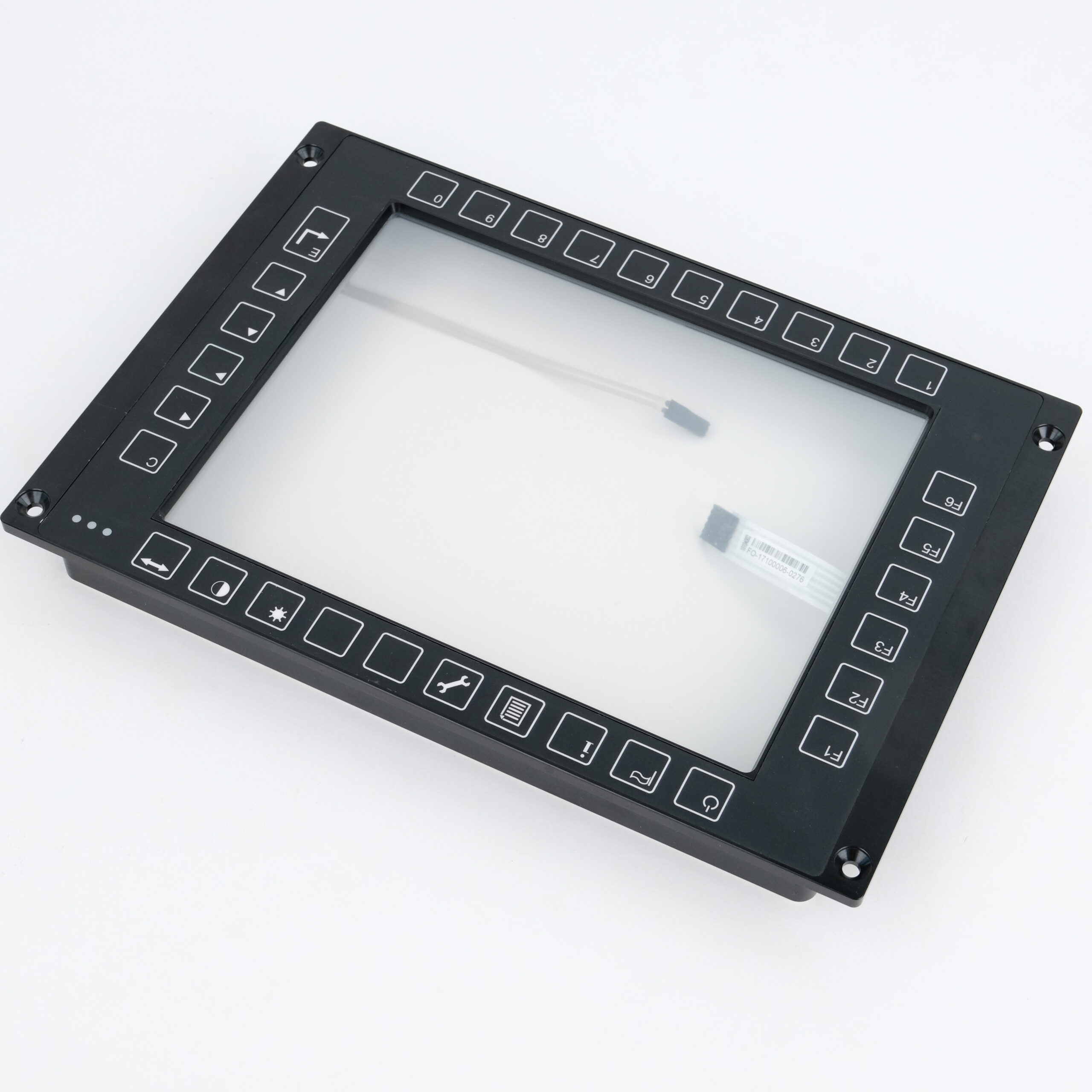
We select and source display, touch, control and connection components around your approved layout, optical bonding requirements and application needs.
Dimensions, interfaces and application requirements.
02 / MATCHED COMPONENTS
An integrated component set, reviewed together.
03 / VERIFIED SUPPLY PACKAGE
Agreed specifications and incoming inspection records.
Select each layer for the same viewing window.
Shown in front-to-rear order. Optical adhesive and spacing are defined for the approved stack; the photographs are individual component references.
OUTERMOST USER INTERFACE
Cover glass / overlay
Define the viewing window, printed key positions, thickness and finish. The existing photo shows the front frame with keypad overlay.
BEHIND THE COVER
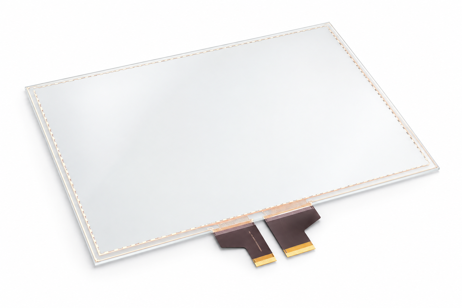
Touch sensor
Evaluate PCAP or resistive touch against the application, cover construction, controller compatibility and intended operation.
BEHIND THE TOUCH SENSOR
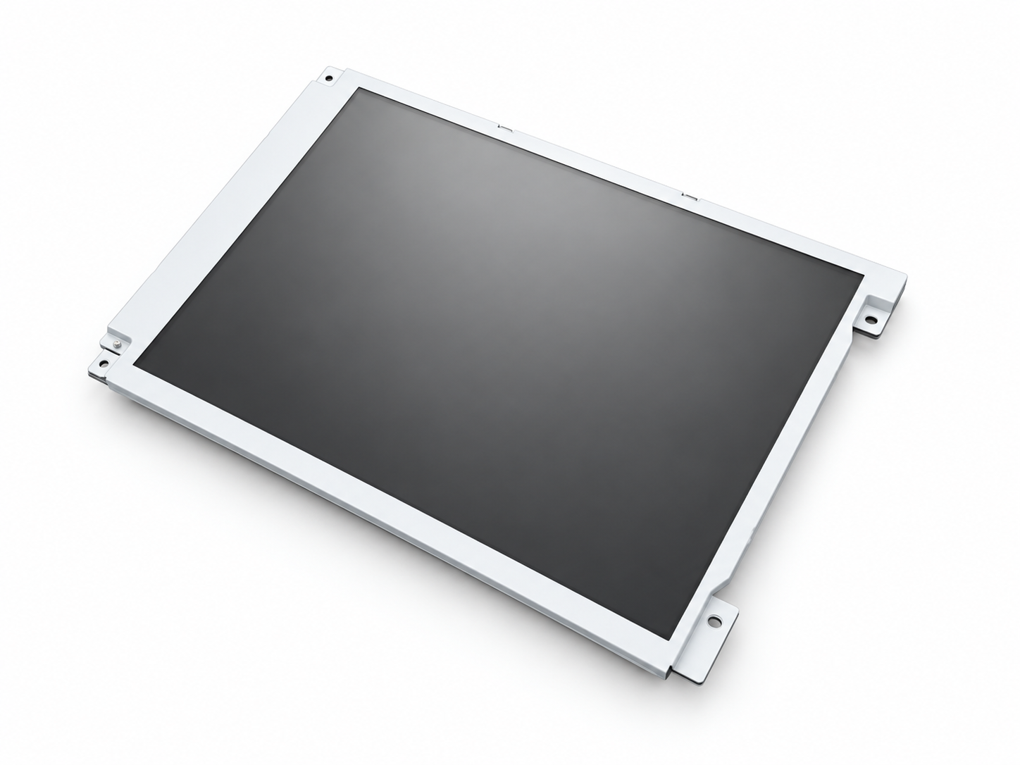
LCD display
Match the active area, overall size, resolution, brightness, interface, backlight and mounting constraints.
Connect the interface to the complete assembly.
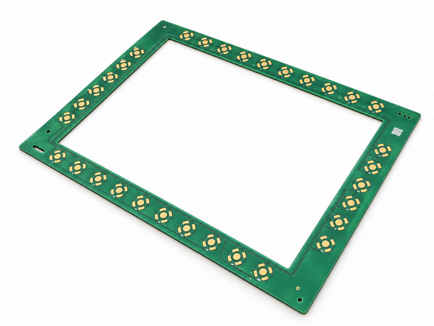
Keypad PCBA
Positioned behind the printed keypad border, with contact locations aligned to the overlay. Review mounting, electrical interfaces and internal clearance.
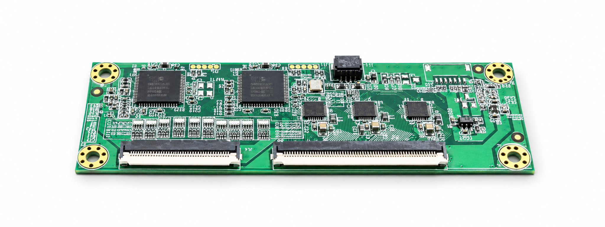
Touch controller
Located behind the touch panel within the enclosure. Match the sensor, host interface, power and FPC connection to the approved layout.
Specify the supporting parts, too.
Cable / FPC / connectors
Define pin assignments, mating parts, cable length, bend space and routing.
Optical bonding material
Select the material and thickness for the optical stack and application conditions.
Seals and mounting hardware
Specify fixings, spacers and any sealing parts required by the agreed structure.
Compatibility first. Supply planned around it.
Availability and alternatives are evaluated for each project; substitutions require review before release.
01 Component compatibility
Review the display, touch sensor, controller and keypad as a connected set.
02 Interface matching
Check signal formats, voltage levels, connectors and pin assignments.
03 Optical and mechanical fit
Check viewing areas, thicknesses, tolerances, fixing points and cable clearance.
04 Long-term availability
Review supplier lifecycle information, lead times and continuity risks for the project.
05 Alternative component evaluation
Assess proposed substitutes against the agreed specifications and approval process.
06 Incoming inspection
Verify received parts against agreed identity, quantity, appearance, dimensional and functional checks.
A defined component set for the next build.
The component selection and sourcing stage supports manufacturing and assembly with a controlled specification and supply package.
Agreed component list and specifications
Compatibility review notes
Reviewed alternatives, where required
Supply and lead-time status
Incoming inspection records
Verified parts released for the agreed build
Inspection scope, documentation and release criteria are confirmed for each project.
NEXT / 03
Metal Structure Manufacturing
Use the confirmed layout and component interfaces to develop the enclosure, mounting and connector features.