





A practical guide to controlled separation, material limits and verification
By VANESEN | Technical Blog | Optical Bonding
Removing a PET functional film from an OCA-bonded touch panel requires control of the separation interface, panel support and peel force. The aim is to remove the PET film and optically clear adhesive (OCA) together while preserving the touch panel (TP), including its film sensor and flexible printed circuit (FPC). Clean separation alone is not enough: the panel must pass inspection and functional checks before reuse.
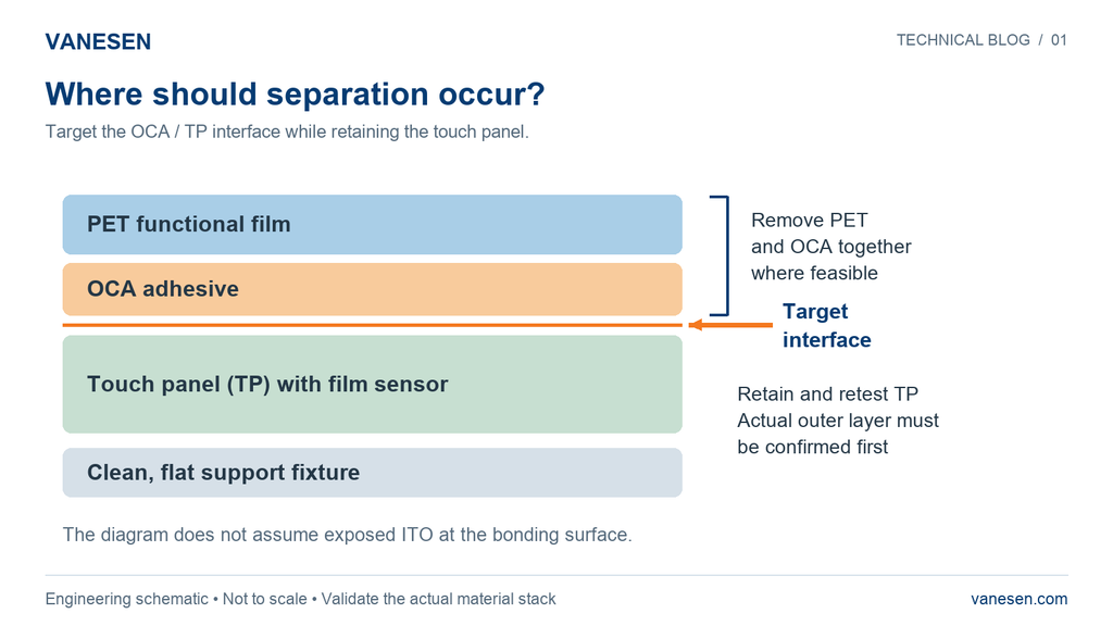
Figure 1. The intended separation is at the OCA / TP interface. The actual TP surface and internal sensor construction must be identified before testing.
Why the material stack matters
The OCA may bond to cover glass, PET with an indium tin oxide (ITO) conductive layer, a hard coating or another surface. The exposed interface cannot be inferred from the name “touch panel.” Local stretching, panel bending or layer separation can affect conductive traces, sensor films and the FPC connection. Adhesive splitting can also leave residue on the retained surface.
What VANESEN has verified
In repeated production work on validated material structures, VANESEN has found controlled separation effective without affecting normal TP function or damaging the surface ITO conductive film when the established operating requirements are followed. This experience applies to those verified structures and conditions. It does not establish a universal process for every TP, OCA or PET combination.
For a new material combination, treat the process as an engineering trial. Use scrap parts or dedicated specimens first. Zero damage and zero residue cannot be guaranteed in advance.
How to approach controlled separation
Start by recording the panel condition and establishing a baseline. Then use a fixture that supports the panel across its full area and allows the peel behavior to be observed and measured.
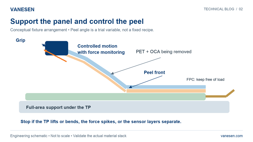
Figure 2. Full-area support and monitored motion help control the trial. The drawn peel direction is illustrative and is not a prescribed angle.
1. Record the baseline. Photograph the assembly and record its batch, bonding date, OCA grade and thickness. Check appearance, touch response, accessible channel resistance and FPC condition before rework.
2. Support the complete panel. Use a clean, flat fixture. Avoid unsupported spans and local vacuum-hole impressions that could deform or stretch a film sensor. Validate the fixture itself before evaluating the peel process.
3. Start away from sensitive features. At an edge away from the FPC and critical traces, use a non-metallic tool to make a small initial lift. Confirm whether PET and OCA can separate together from the TP.
4. Control and measure the peel. Grip the PET and use a fixture with force monitoring to pull at a controlled speed. Keep the peel front as straight as practical and record force against displacement. Manage particles and electrostatic charging during separation.
5. Stop at the first abnormal sign. Stop if the TP lifts or bends visibly, sensor layers separate, peel force rises suddenly, the adhesive tears, the FPC takes load or conductive-layer abnormalities appear. Investigate before continuing.
6. Retest before considering reuse. Inspect the retained panel, residual adhesive, traces and FPC. Complete full-area touch testing and the electrical and reliability checks required for the project.
Define a trial window rather than a fixed recipe
The following conditions are exploratory starting points from the engineering plan. Compare results on the actual materials; do not assume that slower peeling or a particular angle will always cause less damage. Establish the allowable force from the panel structure and test evidence. A universal limit in N or N/cm is not justified without those data.
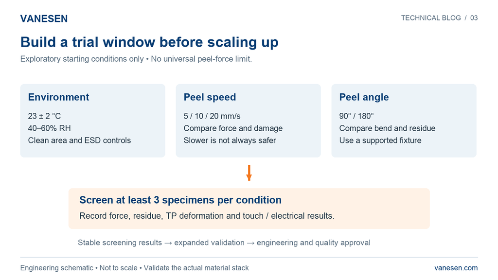
Figure 3. These are starting points for specimen screening, not validated production settings or a statistical qualification plan.
Initial screening conditions are 23 ± 2 °C and 40–60% RH, with peel speeds of 5, 10 and 20 mm/s and angles of 90° and 180°. Maintain clean working conditions, ESD controls and full-area panel support.
What to record in each trial
Record average force, peak force, force variation, the area or proportion of residual OCA, TP deformation, touch failures and rework yield. Use consistent definitions and inspection methods so that conditions can be compared. At least three specimens per condition provide an initial screen only. Expand validation after stable results; this sample count does not demonstrate production reliability.
Heating and freezing require separate validation
Begin with room-temperature trials. If separation is unstable, obtain the OCA and TP material data before evaluating mild heating. Check its effect on peel force, residue and electrical performance. Do not adopt 60–80 °C as a default process window.
Freezing is not the preferred starting route in this plan. Low temperature changes adhesive behavior, and the response depends on the material formulation and stack. Inappropriate temperature, exposure time or peeling can affect the sensor, conductive film or FPC. Qualify compatibility and function before applying a cold process to production parts.
Qualify adhesive removal chemicals
Any solvent used for residual adhesive requires separate compatibility checks with PET, ITO, hard coatings, inks and FPC adhesives. Do not immerse the TP in an unvalidated solvent. Residue that cannot be removed within the approved process is a reason to hold the part for engineering review.
Verify the touch panel before release
Judge the reworked panel against the original product requirements and its recorded baseline. The release decision must consider electrical and touch performance as well as appearance.
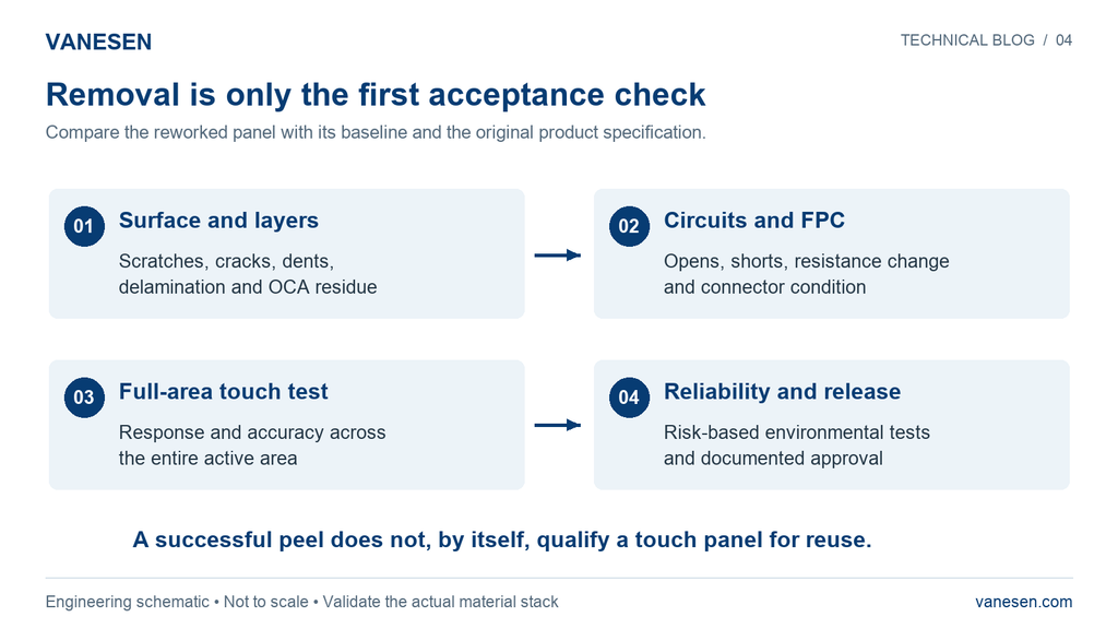
Figure 4. Reuse depends on inspection and functional verification, followed by the required reliability review and approval.
Inspect for scratches, cracks, dents, delamination and unacceptable residue. Check for open or short circuits and resistance changes outside the product specification. Verify touch response and accuracy across the full active area, and inspect the FPC for looseness, fractures or signs of abnormal loading.
Engineering and quality should determine the environmental or life tests needed from the rework risk and customer requirements, then approve release using the documented results. First-piece validation, process monitoring and post-rework inspection remain necessary even when the method has worked on an earlier project.
Information needed before a project trial
- TP outer surface, total thickness, sensor construction such as G+F or G+FF, FPC location and allowable bending or strain.
- OCA manufacturer, grade, thickness, bonding age, curing or aging condition where applicable, and supplier rework guidance.
- PET film thickness, surface treatment and coating details.
- Whether the TP will be bonded again, plus the customer’s inspection and acceptance requirements.
Changes to the TP structure, ITO surface treatment, OCA grade or thickness, PET material or peel conditions require renewed validation. Do not extend an approved process to an unverified combination without engineering and quality approval.
Discuss your display stack with VANESEN
Share your layer structure, material details and rework objective with VANESEN to discuss the engineering review needed for your assembly. For related guidance, read What Is Optical Bonding? and Display Integration for Industrial HMI on our Technical Blog.
What Is Optical Bonding? | Display Integration for Industrial HMI | Discuss your project
One Response