
INDUSTRIES / RAILWAY
Railway HMI Integration for Driver Consoles
Application Environment
Confirmed application: the existing VANESEN keypad HMI is installed in a railway driving-cab console.
The supplied application information places the HMI at the driver’s operating desk. The front provides the display, touch surface and physical keys; mounting and electrical access sit behind the console. The supplied test-bench photograph shows the delivered product family, rather than an in-cab installation.
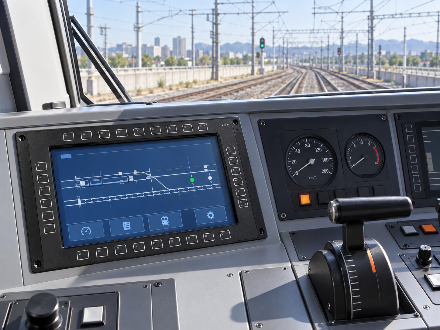
AI-generated application illustration.
Temperature & front protection
The stated −40 to +85°C range is treated here as a storage requirement for the referenced project, not as a powered operating-temperature rating. Powered limits, duration and post-storage checks must be defined for the selected assembly. Front ingress protection must be assessed with the actual console mounting and seal.
02 / APPLICATION CHALLENGES
Display & HMI Challenges
Cab viewing conditions
Daylight entering through cab glazing and night-time operation create different reading conditions. Review viewing angle, reflections and dimming at the driver’s eye position; no numerical luminance specification has been supplied.
Two complementary input methods
The photographed HMI has a touch window and physical keys around it. Each key needs an agreed assignment and press/release response; touch areas need position and tracking checks on the complete assembly.
A stable console installation
Review the mounting points, frame support, cable restraint and access behind the driver’s desk. Vehicle vibration requirements must be addressed at the installed-assembly level.
Protection at the front boundary
The intended protection boundary is the installed front face. The cover-to-frame joint, key interface and console gasket must work together; rear connectors and the surrounding desk are separate interfaces to resolve.
03 / INTEGRATION STRUCTURE
Recommended Integration Approach
Front panel and optical stack
Retain the established front-panel layout and the customer’s key positions. Coordinate the cover or overlay, touch sensor, LCD and metal frame around the available desk opening. Select optical bonding only where the chosen stack and optical requirements support it.
Keypad and touch integration
Define the physical key map independently of the touch input. Select the controller, wiring and host connections for the actual configuration; verify that the assembled front surface preserves the intended input response.
Mechanical support and front seal
Review glass support, LCD fixing points, perimeter gasket compression and the console mating surface together. Maintain service access and cable routing behind the desk without assuming the rear space has the same protection as the front.
Configuration-specific qualification
Specify storage and powered operation separately. Define front ingress protection and vehicle-specific vibration or electrical requirements for the mounted configuration before describing it as qualified.
04 / DELIVERY FORM
Typical Delivered Assembly
Existing keypad HMI on the functional test bench. Photograph supplied by VANESEN.
Confirmed delivery form: the complete keypad HMI shown in the supplied test photographs, for integration into the driver’s console.
• A display window with integrated touch input
• Physical keys arranged around the display perimeter
• A coordinated front frame and rear housing
• The product connection arrangement defined for the actual customer configuration
The exact bill of materials, interface types and numerical operating specifications were not supplied. They should be confirmed for the referenced unit; vehicle-control software and vehicle-level approval are not implied.
Evidence boundary: the documents currently supplied do not establish an IP65 pass for this configuration. Protection claims will be updated when the applicable passing report and installation scope are confirmed.